- Overview
- Background
- Affected Vehicles
- Symptoms
- Causes
- Internal Oil Pressure Loss (Less Common)
- System Components (Parts Overview)
- Recommended Repair Order
- OEM Labeling, Aftermarket Variability, and Verification
- Common Water Entry Point
- Common Mistakes
- Notes
- Quick Diagnostic Flowchart
- 1️⃣ Check Engine Oil
- 2️⃣ Clear Codes and Test Drive
- 3️⃣ Recent Rain or Washing?
- 4️⃣ Inspect VTEC Electrical Connectors
- 5️⃣ Inspect Primary VTEC Filter Screen
- 6️⃣ Inspect Secondary VTEC Filter Screen (If Needed)
- 7️⃣ Verify Mechanical Oil Pressure (Less Common)
- 8️⃣ Replace VTEC Solenoid Assembly (Last Resort)
- References
- Key Takeaway
- Revision History
- Contributors
Overview #
Honda Element VTEC limp mode is a reduced-power operating condition triggered when the engine control unit (ECU) detects a fault within the Variable Valve Timing and Lift Electronic Control (VTEC) system. On the Honda Element, this condition is most commonly associated with diagnostic trouble codes (DTCs) P2646 and P2647.
When limp mode is active, engine performance is intentionally limited to protect internal components. In the Element, the underlying cause is most often related to oil pressure feedback issues or electrical faults involving the VTEC oil pressure switch, the VTEC solenoid assembly (commonly called the spool valve), or their associated wiring.
Background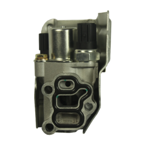 #
#
The Honda Element uses Honda’s i-VTEC system to improve engine efficiency and performance by varying valve timing based on engine load and oil pressure. Proper VTEC operation depends on several factors, including correct oil level, adequate oil pressure, clean oil passages, and accurate electrical feedback to the ECU.
Over time, exposure to moisture, heat, and oil contamination can degrade electrical connectors and internal filter screens within the VTEC system. These conditions may result in intermittent or persistent limp mode behavior.
Read about the differences between the VTC and VTEC in VTC vs VTEC — They Are Not the Same
Affected Vehicles #
Honda Element
- Model years: 2003–2011
- Engines:
- K24A4 (2003–2006)
- K24A8 (2007–2011)
- Drivetrain: FWD and AWD
- Transmission: Manual and automatic
Symptoms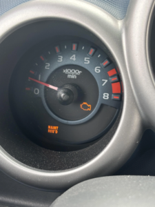 #
#
Common symptoms include:
- Sudden loss of engine power
- Engine speed limited to approximately 3,000 RPM
- Hesitation or bucking during acceleration
- Illumination of the Check Engine Light
- Stored DTCs P2646 and/or P2647
- Temporary return to normal operation after restarting the vehicle or clearing the code
Causes #
Known causes of VTEC limp mode on the Honda Element include:
- Faulty VTEC oil pressure switch
- Corrosion in the oil pressure switch electrical connector
- Corrosion in the VTEC solenoid electrical connector
- Low, contaminated, or incorrect engine oil
- Blocked oil passages or clogged VTEC filter screens
Internal Oil Pressure Loss (Less Common) #
In a smaller number of cases, VTEC-related diagnostic trouble codes may be triggered by insufficient engine oil pressure rather than electrical faults.
Potential mechanical contributors include:
- Excessive bearing clearance due to bottom-end wear
- A failing or worn oil pump
- General engine wear affecting oil pressure at operating temperature
When oil pressure is marginal, the VTEC system may fail to achieve the pressure threshold required for proper operation, resulting in incorrect oil pressure feedback to the ECU and limp mode activation.
Mechanical oil pressure issues are significantly less common than connector-related failures on the Honda Element and are typically evaluated only after electrical integrity and oil flow restrictions have been ruled out.
System Components (Parts Overview) #
Several components work together to control VTEC operation. Understanding these parts helps reduce the likelihood of misdiagnosis.
VTEC Solenoid Assembly (Spool Valve)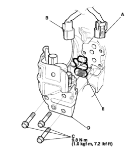 #
#
Honda refers to the VTEC solenoid assembly as the “spool valve.” In service manuals and parts catalogs, the terms VTEC solenoid assembly and spool valve assembly are used interchangeably.
The assembly contains multiple internal components, including oil control passages, internal filter screens, and the integrated VTEC oil pressure switch. Failures attributed to the “VTEC solenoid” may originate from any of these internal elements or from the associated electrical connectors.
- Mounted on the firewall side of the engine (passenger side)
- Secured with three 6 mm bolts using 10 mm hex heads
Oil Pressure Switch (VTEC Pressure Switch) #
- Integrated into the spool valve assembly
- Uses a round electrical connector with blue and brown wires (B in diagram)
- Most common failure point due to water intrusion and corrosion
VTEC Solenoid Connector #
- Rectangular or oblong connector with a gray interior (A in diagram)
- Typically uses green and black wires
VTEC Filter Screen (Primary) #
- Located between the solenoid assembly and the engine block (E in Diagram)
- Can become clogged with sludge or debris, restricting oil flow
VTEC Filter Screen (Secondary) #
- Located deeper in the oil circuit behind the power steering pump
- Less commonly clogged than the primary screen
- More difficult to access and typically inspected only after other causes are ruled out
Recommended Repair Order #
The following steps are arranged from least invasive and least expensive to more involved repairs. Mechanical oil pressure concerns should be evaluated only after common electrical and oil flow issues have been ruled out.
1. Verify Oil Level and Condition #
Low oil level, incorrect viscosity, or heavily contaminated oil can trigger DTCs P2646 or P2647. Oil level and condition should be verified first. In mild cases, an oil change followed by clearing the codes may resolve the issue.
2. Clear the Code and Monitor #
If oil level and condition are confirmed to be correct, clearing the code with a scan tool may temporarily restore normal operation. This should be treated as a diagnostic step rather than a permanent repair.
3. Moisture-Related Electrical Checks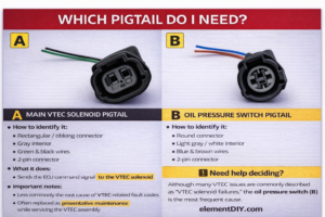 #
#
If symptoms appear after rain or vehicle washing, water intrusion is likely contributing to the fault.
- Disconnect both VTEC-related electrical connectors
- Dry connectors using compressed air
- Apply dielectric grease to reduce future moisture intrusion
- Inspect wire insulation and connector seals
- Apply Hondabond or a high-temperature sealant to the top of connectors if minor insulation cracking is present
- Replace the oil pressure switch pigtail with an upgraded OEM-style sealed harness if corrosion is present
4. Inspect for Oil Flow Restrictions #
Primary Screen (Spool Valve Screen)
- Remove the solenoid assembly using a 10 mm socket
- Ensure the socket is fully seated on angled bolt heads to avoid rounding
- Inspect the screen for debris or damage
- Replace if clogged or torn (Honda part number: 15815-RAA-A02)
Secondary Screen (Behind Power Steering Pump)
- Requires removal of the drive belt and power steering pump
- Inspection recommended only if the primary screen shows significant contamination
- Honda part number: 15845-RAA-A01
5. Replace the VTEC Solenoid Assembly #
Solenoid replacement should be considered a last resort after confirming oil supply and electrical integrity.
- Use genuine OEM components whenever possible
- Verify supplier authenticity before installation
- Torque mounting bolts to approximately 7.2 lb-ft
OEM Labeling, Aftermarket Variability, and Verification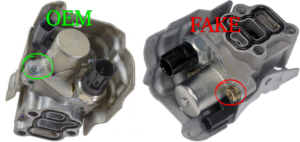 #
#
Replacement VTEC solenoid assemblies are widely available through aftermarket suppliers and online marketplaces. Some listings are described as “OEM” or “OEM-style,” and may display images of genuine Honda parts. However, the component shipped may differ from the original OEM assembly.
Community-documented cases show that solenoid assemblies marketed as OEM can differ in internal tolerances, sealing quality, electrical characteristics, or connector construction. These differences may not be visually obvious prior to installation and can result in intermittent oil pressure feedback or recurring diagnostic trouble codes.
Because visual inspection alone is often insufficient, verifying part numbers, packaging, supplier authenticity, and return policies can help reduce the risk of repeat failures or misdiagnosis.
Common Water Entry Point #
A frequent source of moisture intrusion is the passenger-side windshield washer nozzle.
- Positioned directly above the VTEC solenoid area
- Rubber gasket can deteriorate over time
- Allows water to drip directly onto VTEC connectors
Removing the nozzle and sealing the opening with silicone or a suitable sealant can significantly reduce water exposure.
Common Mistakes #
Common diagnostic and repair errors include:
- Replacing the VTEC solenoid without inspecting the oil pressure switch or wiring
- Ignoring visible connector corrosion
- Mistaking the issue for a transmission failure
- Clearing codes without addressing the underlying cause
Notes #
Some vehicles may experience intermittent symptoms for extended periods before limp mode becomes persistent. Environmental exposure and water intrusion appear to accelerate connector-related failures.
Quick Diagnostic Flowchart #
Honda Element VTEC Limp Mode (P2646 / P2647)
Use this checklist to identify the most likely cause before replacing parts.
1️⃣ Check Engine Oil #
Is the engine oil level correct and the oil reasonably clean?
-
❌ No →
Correct oil level and/or change oil → Clear codes → Test drive -
✅ Yes →
Proceed to Step 2
2️⃣ Clear Codes and Test Drive #
After clearing the code, does limp mode return during a short drive?
-
❌ No →
Intermittent issue; continue monitoring -
✅ Yes →
Proceed to Step 3
3️⃣ Recent Rain or Washing? #
Did the issue occur after rain, car washing, or wet conditions?
-
✅ Yes →
Proceed to Step 4 -
❌ No →
Still proceed to Step 4
(Water intrusion is often hidden or delayed)
4️⃣ Inspect VTEC Electrical Connectors #
Disconnect and inspect:
-
VTEC oil pressure switch connector (round)
-
VTEC solenoid (spool valve) connector (rectangular)
Is corrosion, moisture, or oil contamination present?
-
✅ Yes →
Repair or replace affected pigtail(s) → Clear codes → Test drive -
❌ No →
Proceed to Step 5
5️⃣ Inspect Primary VTEC Filter Screen #
Remove the VTEC solenoid (spool valve) assembly and inspect the primary filter screen.
Is the screen clogged, torn, or restricted?
-
✅ Yes →
Clean or replace screen → Reinstall → Clear codes → Test drive -
❌ No →
Proceed to Step 6
6️⃣ Inspect Secondary VTEC Filter Screen (If Needed) #
Inspect the secondary filter screen behind the power steering pump
(recommended only if contamination is suspected)
Is the screen blocked?
-
✅ Yes →
Clean or replace → Test drive -
❌ No →
Proceed to Step 7
7️⃣ Verify Mechanical Oil Pressure (Less Common) #
If all electrical and oil-flow checks pass:
-
Perform a mechanical oil pressure test
-
Evaluate for:
-
Oil pump wear
-
Bottom-end bearing wear
-
Is oil pressure below specification?
-
✅ Yes →
Address mechanical oil pressure issue -
❌ No →
Proceed to Step 8
8️⃣ Replace VTEC Solenoid Assembly (Last Resort) #
Replace the VTEC solenoid (spool valve) assembly only after confirming:
-
Good wiring and connectors
-
Adequate oil flow
-
Acceptable mechanical oil pressure
Use verified OEM components when possible.
References #
- Installation Video: Honda Element K24 Spool Valve Connectors Installation Guide by Classic Automotive NC https://www.youtube.com/watch?v=qpRC_W2fLk8&t=2s
Key Takeaway #
Most Honda Element VTEC limp mode issues are electrical or oil-flow related, not mechanical engine failures.
Following a structured diagnostic order prevents unnecessary part replacement and misdiagnosis.
Revision History #
- v1.0 — Initial article creation
Contributors #
- Element DIY
- Classic Automotive NC
Suggest an edit to this article #
Spotted something incorrect, outdated, or unclear? Submit a correction or suggestion to help keep Elementopedia accurate.
Tip: If you can, include the section name and a source or link.
Submissions are reviewed before changes are made. Not all suggestions will result in edits.
Disclaimer & Use Notice
This article is provided for informational purposes only. Vehicle configurations, part availability, and repair procedures may vary by model year, trim level, region, and prior modifications. Always verify part numbers, specifications, and procedures using official manufacturer documentation, and consult a qualified technician when appropriate.
Vehicle modifications, repairs, and installations may be subject to local, state, or federal laws and regulations. Not all modifications described may be legal or permitted in all jurisdictions. It is the responsibility of the reader to confirm compliance with applicable laws and safety requirements before operating a modified vehicle.
The author and publisher assume no responsibility for damage, injury, loss, or legal consequences resulting from the use or misuse of information contained in this article.
Affiliate & External Links Notice
Some articles may include links to external products, services, or retailers. In certain cases, the owners or contributors of this site may have an affiliation with these vendors or may earn a commission from qualifying purchases made through such links. These links are provided for reference and convenience only and do not constitute an endorsement. Product availability, pricing, warranty terms, and return policies are determined solely by the external vendor.


